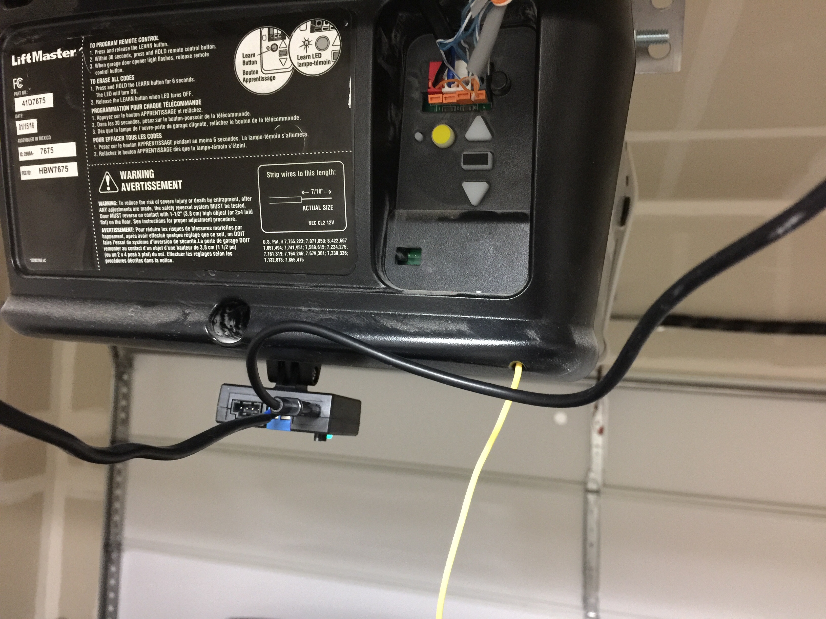
Connect the two wires from the Garadget’s blue terminal to the red and white terminals on the garage door opener. Garadget’s wires will have to share the terminals with the existing wires connecting the wall button. To insert or release wires from the terminal, push in the tab with screwdriver tip.
Mine is connected by wire to a wall mounted opener. On the App, I click to close the up arrow on the garage unit blinks and the wall mount light turns off. I hear the relay and nothing happens. On the App, I click to open the down arrows on my garage unit blinks. (sounds backwards) Seem like the garagdget is sending the wrong signal and causing my wall mount to turn off also. I tried unwiring my wall mount and had only the garagdget. No go.
Also tried switching the wires blue to black to see if it mattered.
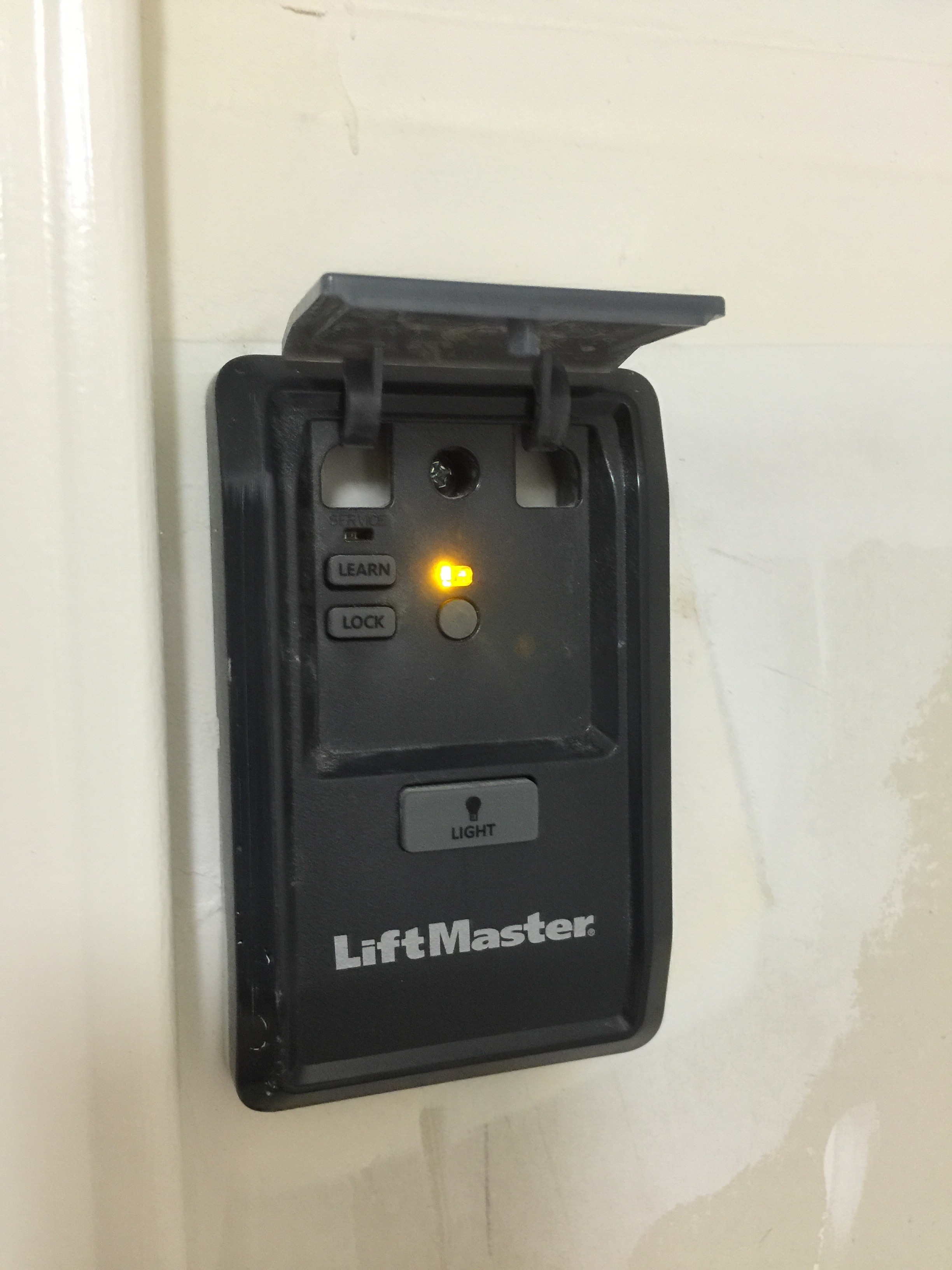
When i use the wall mount the light button never turns off.
Maybe my garage is too smart for garadget? The wall mount utilize only two wires to turn lights on/off, garage up/down, lock, and learn.
Switching between two of the wires will not have any effect because inside of Garadget there is a relay that just mechanically connects the contacts for short time. If wiring is correct, then shorting together two wires that you prepared for Garadget should get the door in motion.
Also in Garadget settings it is possible to adjust the duration of the simulated button press, please see if different values have any effect.
I know it wouldnt have done anything switching the two. Just wanted to let you know i tried all of the things i could think of. Forgot to mentioned that i tried shorting also which is a no go. The wall mount must be using different signals or strength to get it to go. The garage reaponds to the electricity but it doesnt understand garagdget. Two wires being able to control four functions would need to have signals and not just power running through it. Maybe we can have the relay go off like a signal to get it to work.
Maybe ill put a volt meter on the wallmount openener button and see if it fluctuates.
I happen to have a LiftMaster at home, and though it also has light and radio lock on the wall button, shorting the two contacts operates the door. @xNinjas, what is your opener’s model? Also any info about the button would be helpful (picture etc).
Thanks for the info.
LiftMaster Model 882LM Multi-Function Control Panel is Security+2.0. There’s a paragraph about it in the installation instructions under “Wiring Research”.
Connecting Garadget directly to the opener doesn’t work because the the openers enabled with Security+ 2.0 (MyQ and AssureLink models from LiftMaster, Chamberlain and Sears) can’t be triggered with a toggle. They must use the encrypted serial protocol supported by remotes like the 882LM.
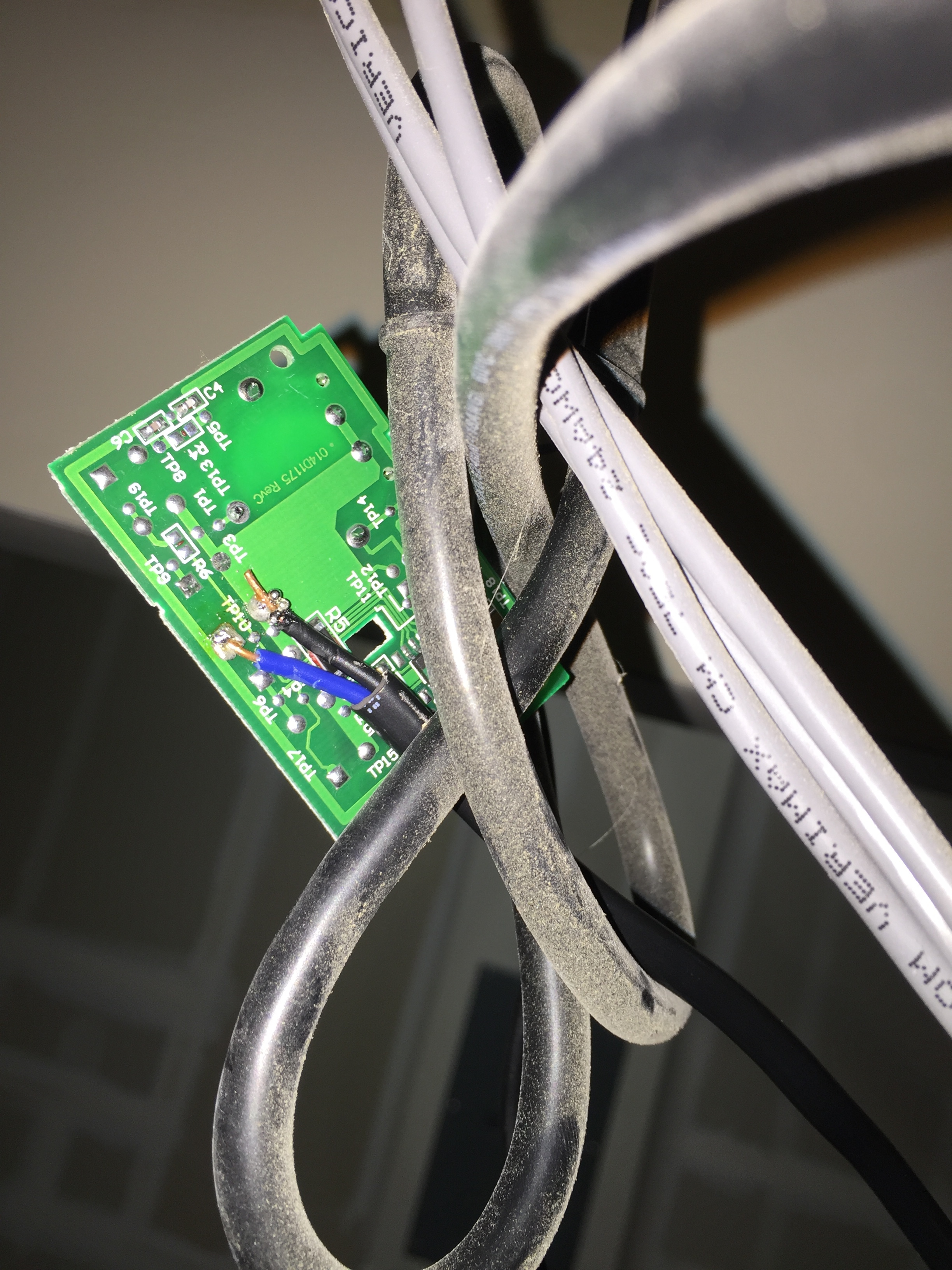
Wiring Garadget to the button pads of a spare wireless remote or wall remote are the valid solutions for this. Essentially Garadget’s relay will be pressing the remote control’s button for you.
That should do it. Please share more pics when finished.
I get the need for extended functions on the wall panel and the move to the serial protocol as the result, but I see no reason for removing the terminals for traditional wall button. It’s almost as if they are trying to secure+ the sales of their own products. /rant
Ha, will do. Moving forward since more and more utlizing this style. Might want to offer an addon for these paticular models where we don’t have to go out and buy a spare remote and hack it
Why won’t a software fix be introduced? There should be a way around this kind of security+.
I don’t have a spare remote as both are used in this household.
Did I buy a product that won’t work on my door because the manufacturer of the door opener uses a security protocole?
It’s not a technical limitation; the manufacturer of your opener will sue anybody who tries to talk to their units.
Please view this topic for explanation and workaround.
Part of the motivation for Garadget was to put pressure on vendors of other garage door controllers to open their protocols and allow people to use the devices their purchased in any way they see fit.
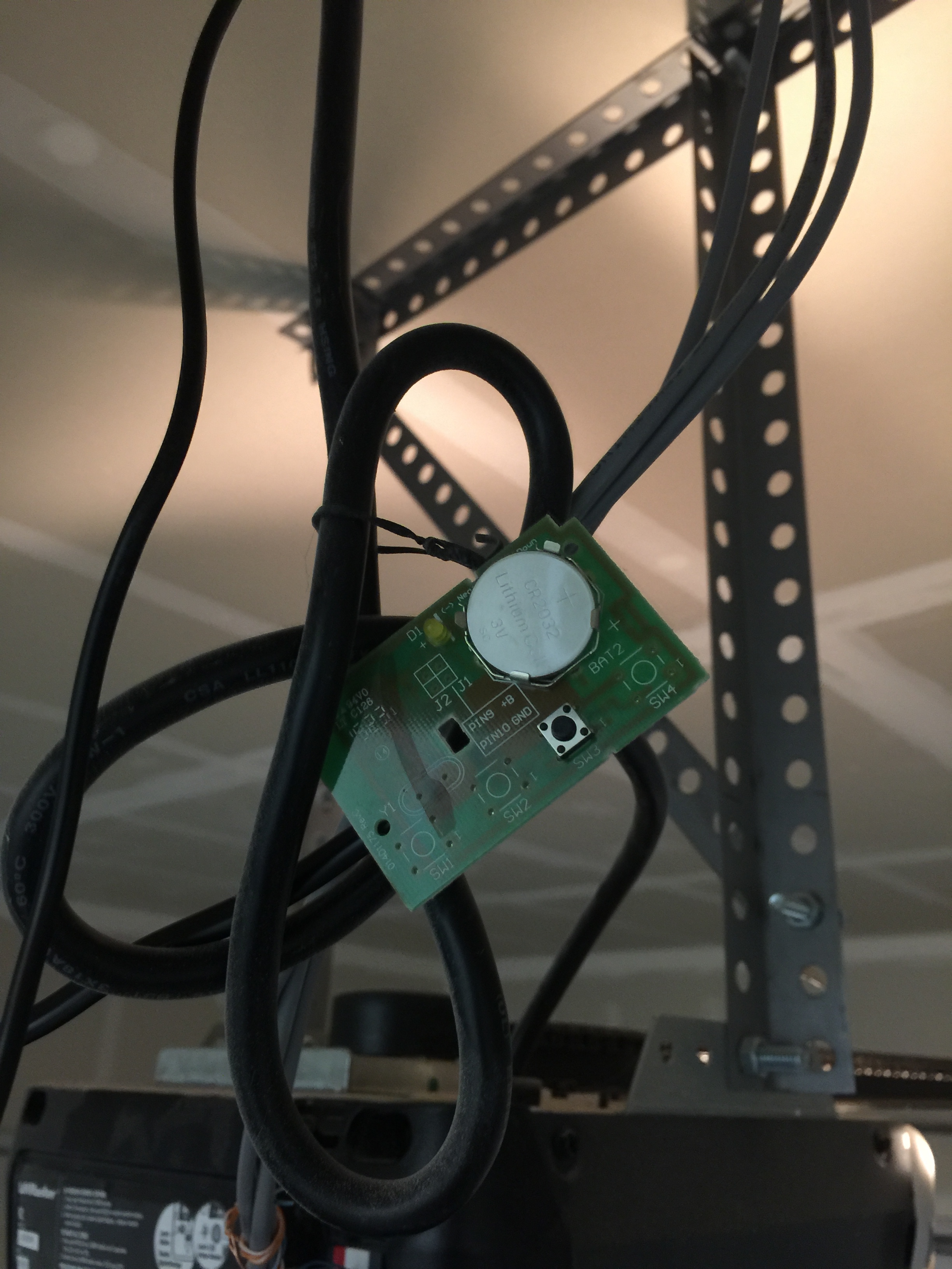
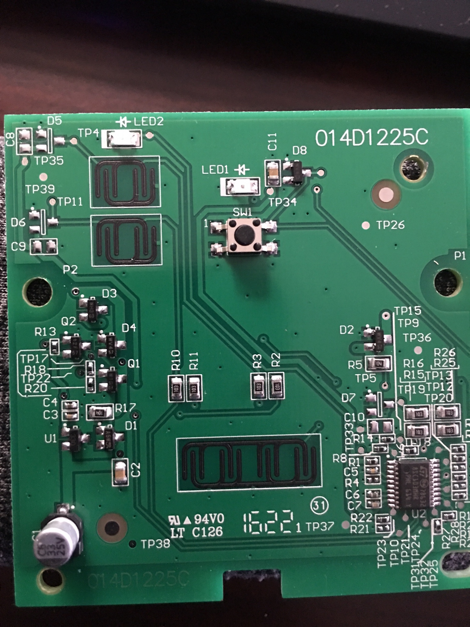
Thanks for these instructions - it seems xNinjas used a circuit board from a remote control. I purchased a 882LMW wall button - will the 'work around" work with a wall button or do I need a remote control circuit board? If the wall button works, does anyone know where I can find a wiring diagram? I see where the button is on the board, but don’t know which of the leads I should solder to in order to create the proper connection. Since I have the wall-based controller board, I assume I would use the screw-points to go from the board to the back of the opener and the Garadget leads would be soldered to the “button” points on the board.
I see one surface mounted button and 3 groups of contacts for the rubber membrane type of button. There is no picture of the front panel so without the labels I’ll have to guess that the surface mounted one is for operating the door.
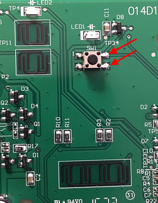
You are correct @garadget the rubber membrane is for other options. @busbys you’d want to test out on "SW1"
The way I determined which leads to solder i used the little screw drive that came with the garadget.(use any metal and see which one will work) then I solder the back leads with the wires from garadget.
BTW @busbys how is that thing powered? and is it connected to the garage?
Thank you all for your help with this. @xNinjas - It would get it’s power from the opener - same as the wall button. It’s still a guess on if the opener will be confused by hooking up two wall buttons. I might have to go find the wireless controller like you have if this does not work.
I will post once I get a chance to test this and let you know if it works. Thanks!
@garadget I think you are right - P1 and P2 are the two screw terminals which wires from the opener would be attached. I will take the leads from the garadget and solder to the SW1 terminals and then solder a another patch cable from P1 and P2 and run to the opener. I think that should power both the wall button and the circuit board.