I have 2 liftmasters, one is newer with security 2.0, but I don’t have MQ2. I have dozens of controllers I’ve made from arduino, esp, or raspberry pi. I built a controller with a camera, temp, humidity, motion along with a relay for operating as a button. Everything works great on the older model. I see with security 2.0 I’ll have an issue sending the right voltage/signal to the motor to operate it. I’m looking for ideas where I can integrate my device before taking a part the button or the motor cover to discover where the signal really translates. However I’m fine with opening one or the other up and soldering in my controller wires, just looking to see where I should start. I’m not worried about wifi security as my network is secure internally and uses ssl outside. Any thoughts? I’m basically looking to bypass security 2.0 to operate through my device in addition to the secure 2.0 devicces. Thanks in advance.
You don’t really want to send any outside voltage/signal to the opener regardless of the opener’s type.
Most openers work with just dry contact (momentarily shorting opener’s control line). With Security+ 2.0 openers you’ll need to use a native remote (standard controller compatible with your opener) and use the dry contact to short the button inside of it. That in turn will cause it to send the signal to your opener.
Ok, perfect. So I’ll take a part the button on the wall and look at the button soldering and figure that out. I’ll report back and let you know how it went. Thanks for the input.
Feel free to send the picture of the button’s internals and I’ll point out where to make connections.
In many cases it is easier to keep the wall console unmodified and use a separate remote as an adapter.
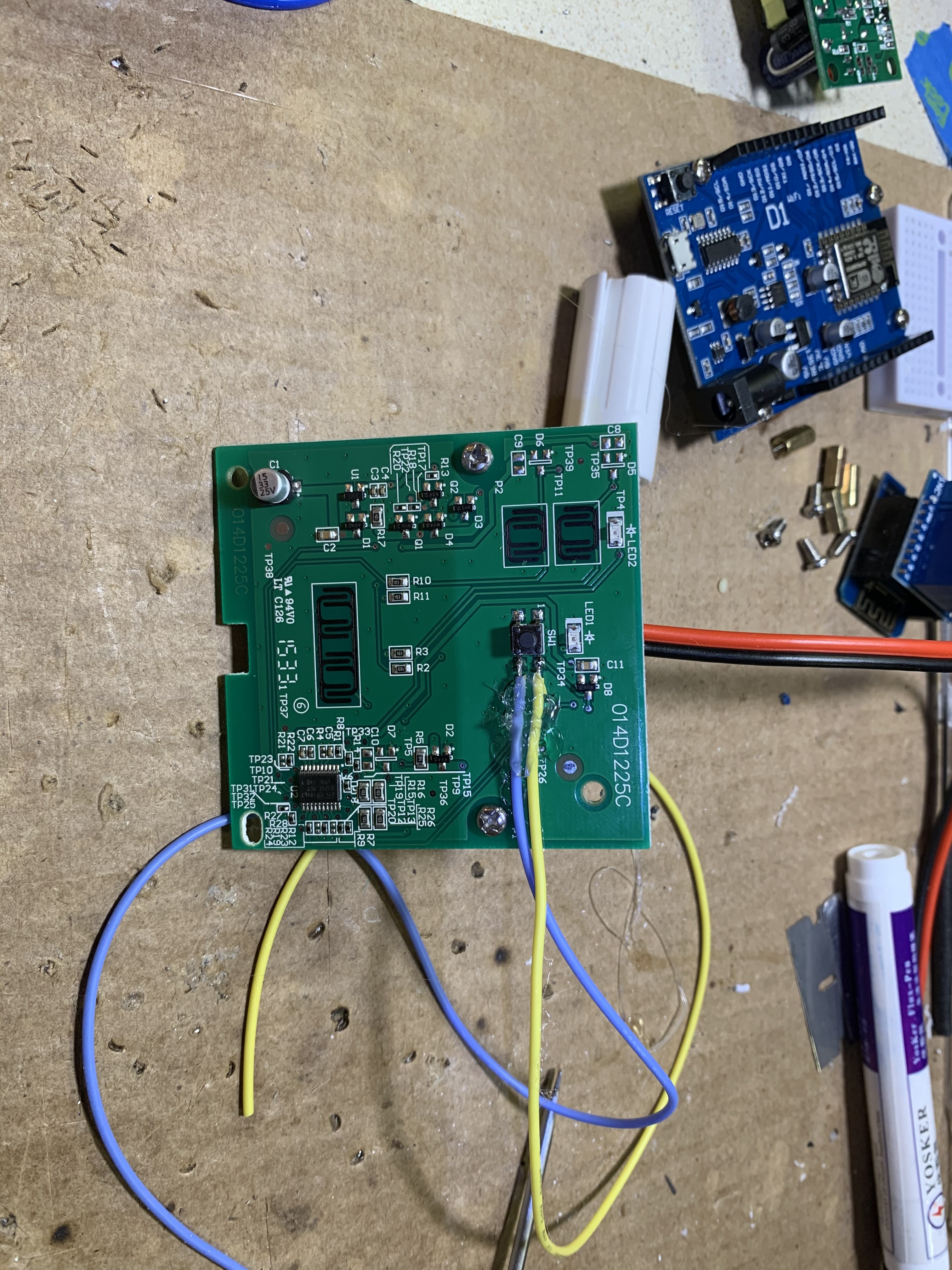
Sorry, jest getting back to this. I found the following image that matches my wall button. Let me know if these are the 2 leads to attach to dry contact for control.
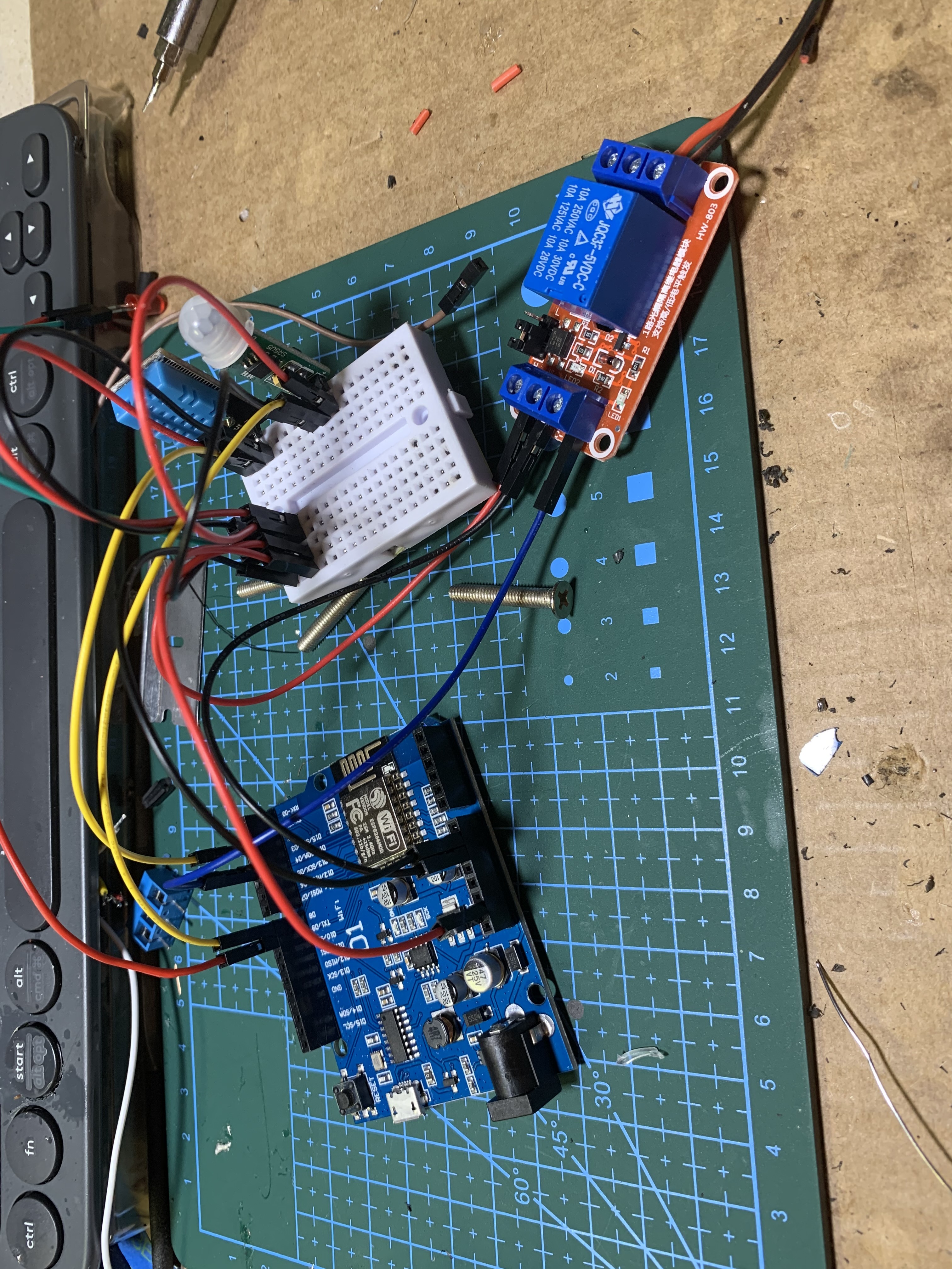
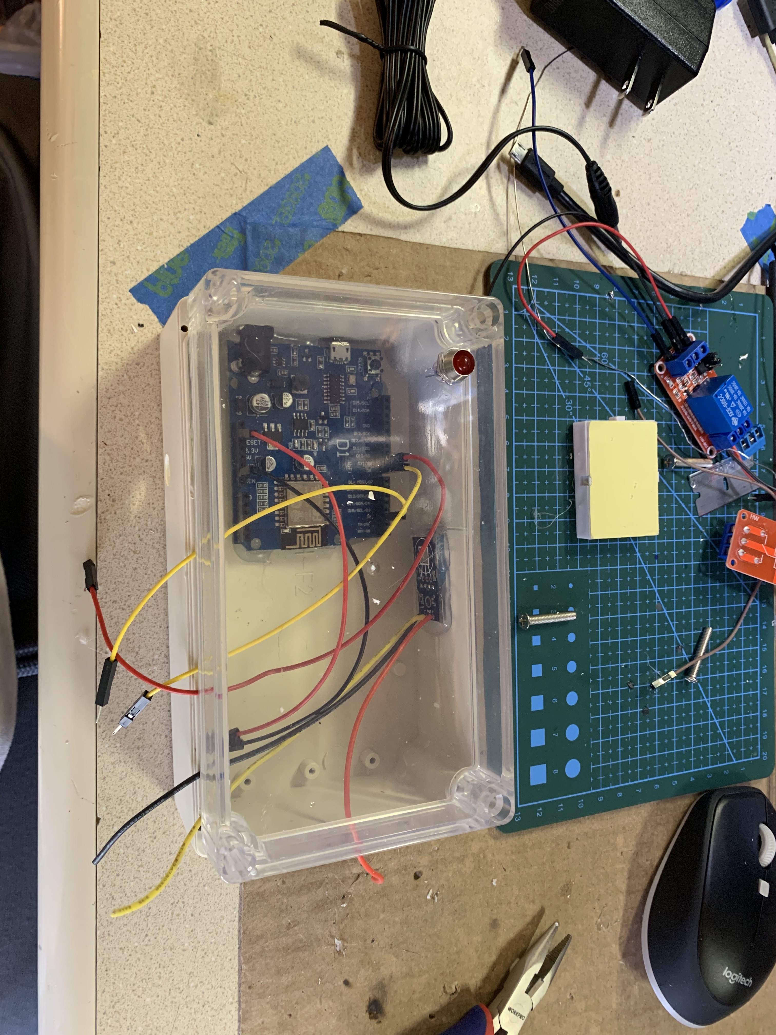
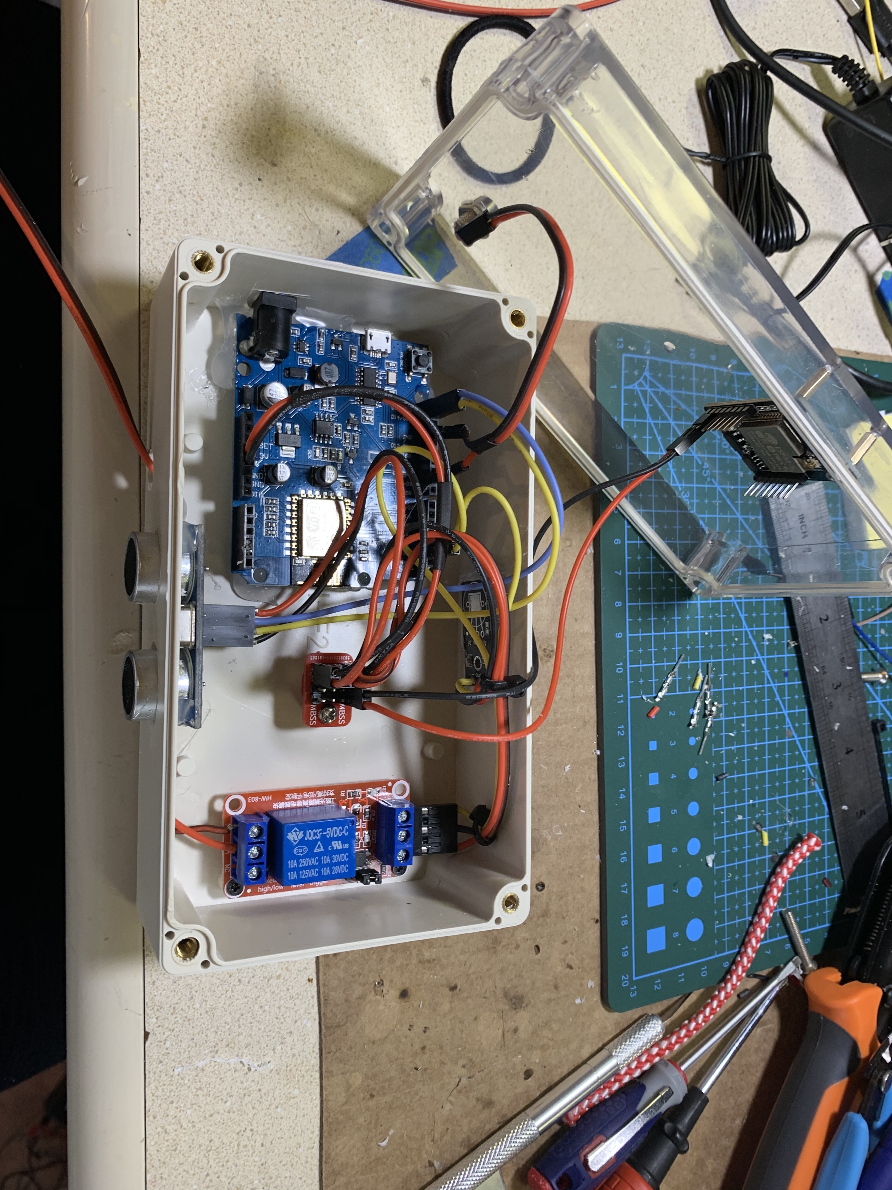
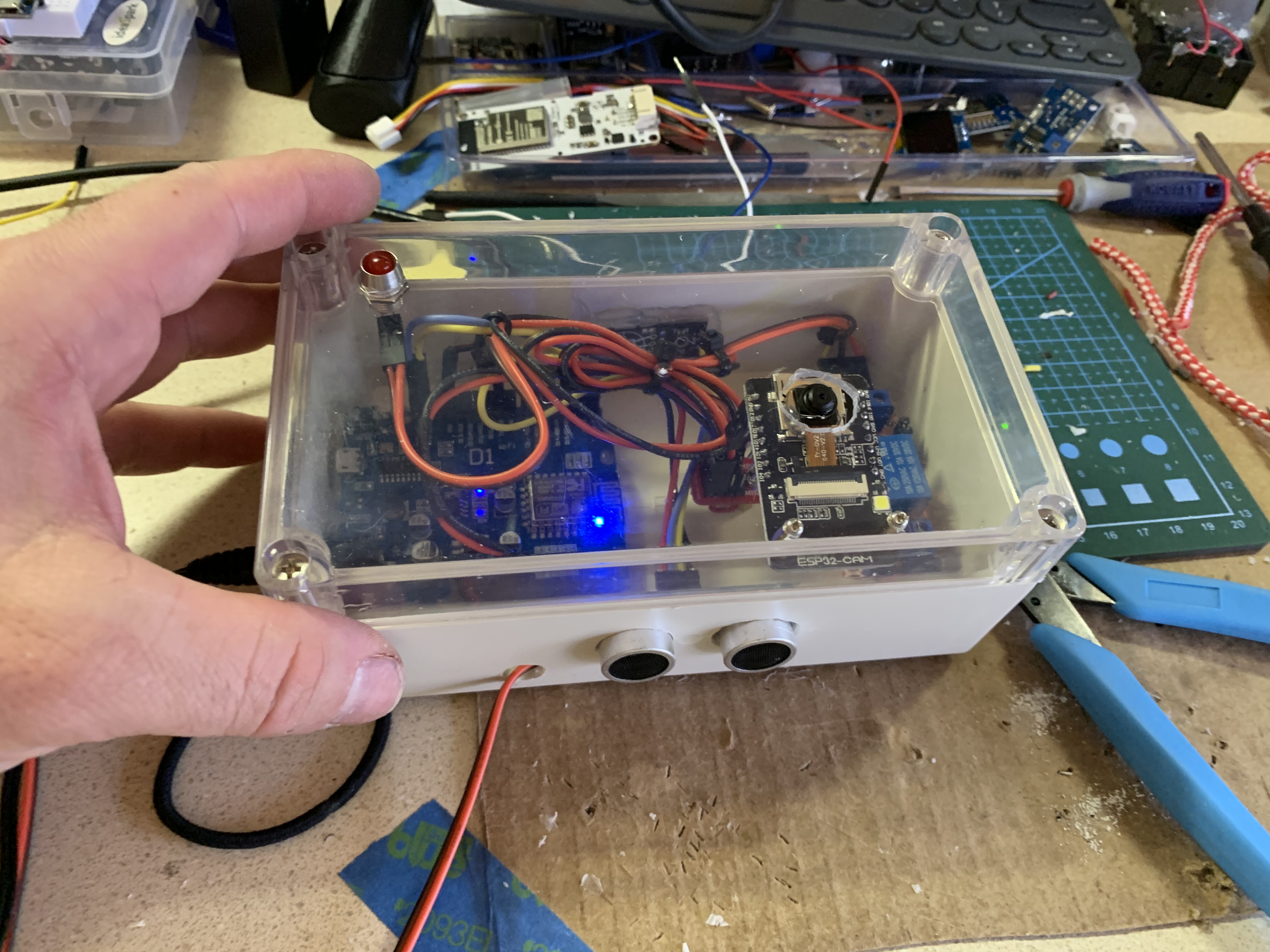
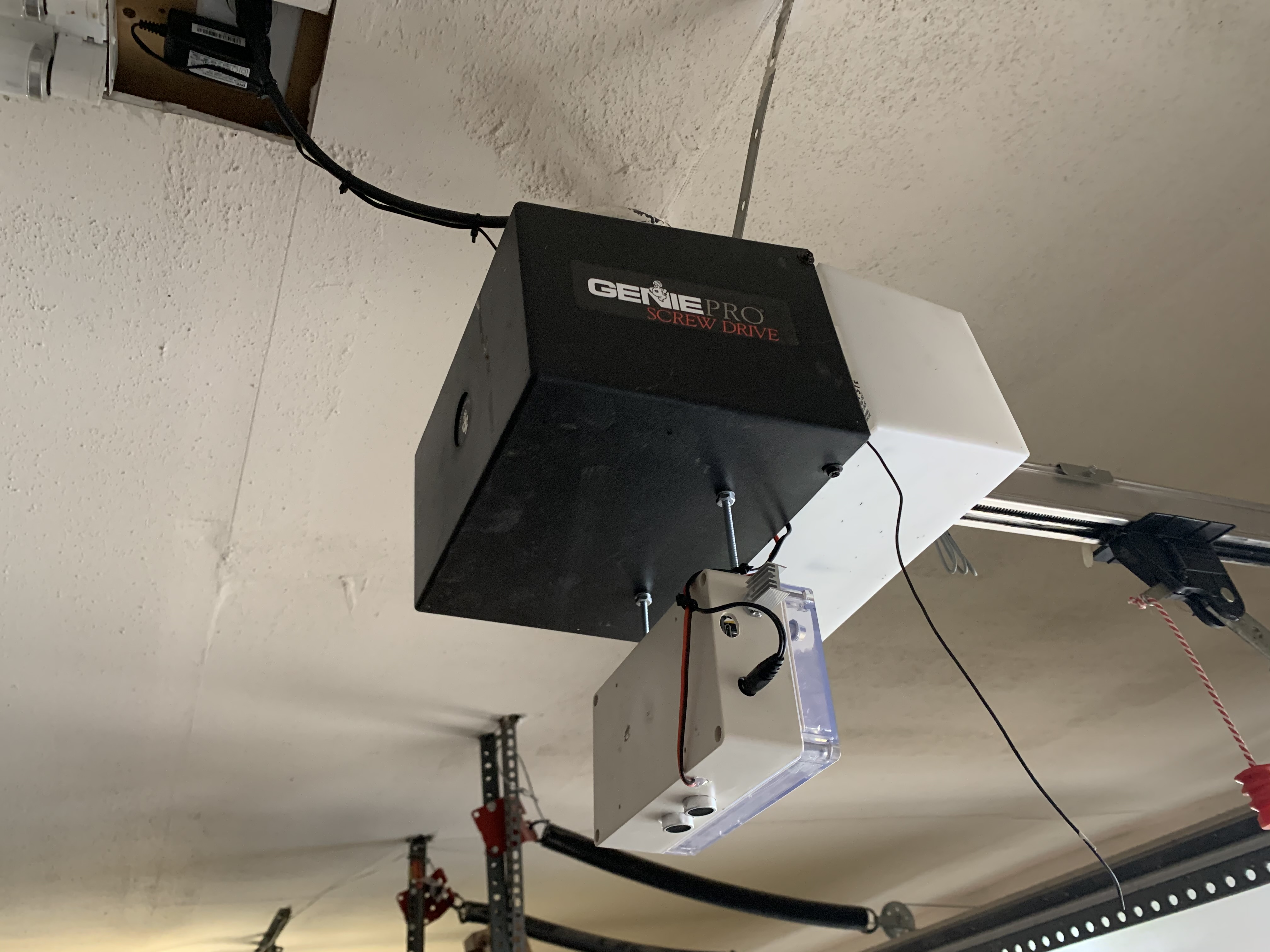
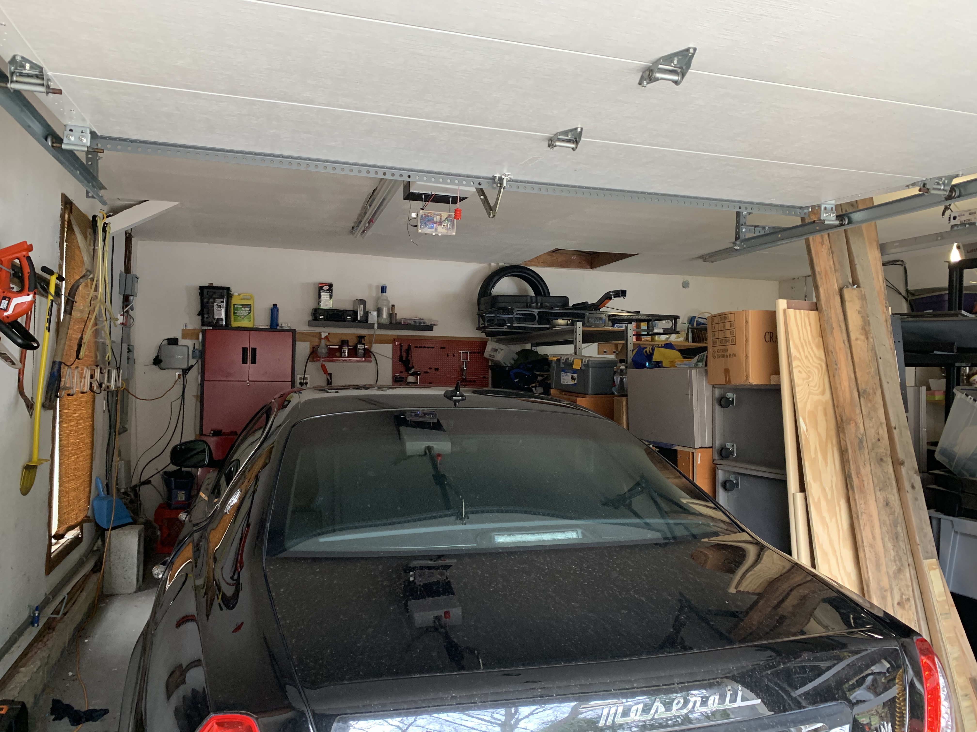
Also, I attached some images of the 1st garage bay device I put together. It’s powered on a 12v wall wart, which powers the Wemos D1 board, which has wifi through an ESP8266 chip. I found that I couldn’t get all my devices working of the onboard 5v feeds even when I used them in parallel. So, I attached a MOSFET 7805 with a heat sink outside the box to feed 5v to a subpanel to power all of my devices. The devices include:
- External ESP32 camera (not attached to D1 since it’s it’s own board)
- Motion sensor
- Temp and humidity sensor
- Red status LED (visually see if there are errors with devices or wifi, series of short, fast, or solid signals)
- Sonar sensor
- I still need to figure out a door open or closed sensor, but for now my app shows the last signal used with a picture of the door open or closed.
From here I have it configured through ESPhome on Home Assistant, which all runs from a Raspberry Pi3 micro board (linux based), but very user friendly web interface for automation.
I have access through my iphone since it’s already configured on Home Assistant (HA)
So here are the automatons I created so far
- The temp & humi are monitored and send me an alert along with web interface alert above 85, bellow 36.
- The sonar tells me a percentage from the distance from the device to the roof of my car, so when it’s parked, it reads 100%. In other words yes my car is there.
- camera alerts me to motion and take a pic
- Garage door opens with app or web interface with virtual button.
*I’m figuring out a way to have the door open when I’m coming down the driveway. Will probably use long range RFID and mount in the nose of my car. This will trigger with in 50’ of the garage.
- 2nd garage door will have less sensors, but I’ll add facial recognition to the camera code and mount that camera along my sidewalk. So that between the hours of noon-4:30PM when my kids get home it will read the face, and open the garage door by the time they get there. It will also play a custom sound or riff inside the house and by the pool so I know who just came home.
I took a few shots of the secure 2.0 button wired. I’ll finish that up tomorrow and post what I came up with.
Thanks for your help


Congrats on the successful build!
Re. opener console connections: that should work
PS: 7805 is technically a voltage regulator, not MOSFET. If you don’t want to deal with heat/losses, consider using a buck converter instead.